 Guest
Guest
Chapter:
1. Explain drag of a Cylinder.
Consider a real fluid flowing past a cylinder of length L and diameter D. the drag coefficient is,
`F_D=C_D*(rho*U^2)/2*A`
Where A is the projected area, which is equal to `LD` for a cylinder.
At very small velocities, `R_e<0.5` the fluid sticks to the cylinder all the way round and never separates from the cylinder. This produces a streamline pattern similar to that of an ideal fluid as shown in figure. The dynamic pressure is achieved at the front stagnation point and vacuum equal to the dynamic pressure exists at the top and bottom where the velocity is at its greatest.
As the velocity increases, the boundary layer breaks away and eddies are formed behind as shown in figure. The drag pressure increases at the front due to the pressure behind and drag pressure drops at the back.
A further increase in velocity cause eddies to elongate and the drag coefficient becomes nearly constant as shown in figure. The pressure distribution shows that ambient pressure exists at the rear of the cylinder.
At Reynolds number of around 90, the vortices break away alternatively from the top and bottom of the cylinder producing a vortex street in the wake as shown in figure. The pressure distribution shows the vacuum at the rear.
Drag Coefficient as a function of Reynolds Number:
For `R_e<1`the flow pattern will be symmetrical.
For `R_e =1 1 to 2000, `C_D` decreases and attains a minimum value of 0.95 at `R_e`=2000.
For `R_e=2000` to `3*10^4`, `C_D` increases and become 1.2 at `R_e=3*10^4`
For `R_e=3*10^4` to `3*10^5`, `C_D` decreases and its value becomes 0.3 at a value of `R_e=3*10^5`
For `R_e=3*10^6`, `C_D` increases and attains a value of o.7 in the end.
2. A jet plane having a wing area of `30 m^2` and weighing 28 KN flies at 900 km/hr. The engine develops 8000 KW and has a mechanical efficiency of 70%. Determine lift and drag coefficient for wind taking density of air as 1.2 kg/`m^3`. [2069-Chaitra ][4]
3. Define aerofoil with accepted terminology with neat sketch. A wing with a span of 22m and 64 `m^2` plan area moves horizontally with a velocity of 760 kmhp. If wing supports 280 KN, find:
- Required value of lift coefficient.
- Induced drag.
Take density of air as 0.526kg/`m^3`.
[2072-Kartik ][8]
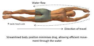
4. Streamlined Body
Streamlined Body:
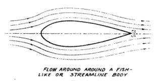
A streamlined body is a body having a shape that lowers the friction drag between a fluid, like air and water, and an object moving through that fluid. In other words, A streamlined body is defined as that body whose surface is aligned with the streamlines, when the body is placed in the flow.
Streamlined body experiences drag mainly due to Viscous/Frictional drag, which depends on the surface area exposed to fluid. Since the drag on the streamlined body is low, the lift/drag ratio is high.In this case, the separation usually takes place at the trailing edge.
An example of streamlined body is a thin aerofoil.
Bluff Body:
A bluff body is defined as that body whose surface is not aligned with the stream-lines, when placed in the flow. Thus, the body offers less resistance in terms of Viscous/Frictional drag. There is a very large pressure drag, due to eddy formation after the body leading to a large wake region. Thus the pressure drag depends on the cross sectional area of the body rather than the surface area exposed.

5. An aircraft weighing 1000 KN when empty has a wing area of 220 `m^2`. It is to take off at a velocity of 300km/hr and a `20^0` angle of attack. Determine allowable weight of cargo and power required for engine. Take density of air as 1.2 kg/`m^3`. Assume coefficient of lift for wing at `20^0` angle of attack as 1.42 and coefficient of drag as 0.17. [2073-Shrawan ][5]
6. A 2mm diameter spherical ball of unit weight 117.5 KN/`m^3` is dropped in a mass of fluid of viscosity 15 poise and specific gravity 0.95. Find out drag force, skin drag and terminal velocity of ball. [2068-Chaitra ][8]
7. A kite has an effective area of `0.6 m^2` and mass 0.4 kg. It experience a drag of 15 N in a wind speed of 40 km/hr. Determine
- tension in chord if it makes an angle of `45^0` with horizontal.
- lift coefficient for kite
Consider density of air as 1.2 kg/`m^3`. [2070-Ashad ][8]
8. Distinguish between pressure and friction drag. Explain with sketches, why airfoil is designed as a streamlined body. [2074-Ashwin ][5]
9. A 2000 kg aircraft is designed to carry a payload of 5000N when cruising at 300 km/hr. The effective wing area is `25 m^2`. Assuming a conventional airfoil, calculate takeoff speed if angle of attack of `10^0` is desired and stall speed when landing. [2071-Chaitra ][8]
10. Explain drag of a Sphere.
Let us consider a case when real fluid flows past a sphere. Let D be the diameter of the sphere, v be the velocity of flow pf fluid of mass density `rho` and viscosity `mu`.
We have,
`R_e=(rho*U*D)/mu`
When velocity of flow is very small or the fluid is very viscous such that the Reynolds number is very small (`R_e<=0.2`), then the viscous forces are more predominant than the inertial force. Stokes analysed theoretically the flow around sphere under `R_e<0.2` and found that the total drag force is,
`F_D=3pimuDU`....(i)
He also found that out of total drag, two third is contributed by skin friction and one third by pressure difference.
Thus,
Skin friction drag`=2/3F_D=2pimuDU`
Pressure drag `=1/2F_d=pimuDU`
Again, the total drag is,
`F_D=C_D*(rho*U^2)/2*A`
Where `A` is the projected area of sphere.
`A=(pi*D^2)/4`
Thus,
`C_D*(rho*U^2)/2*A=3pimuDU`
`C_D=(24mu)/(rhoUD)=24/R_e`
For `R_e` between 0.2 and 5
`C_D=24/R_e(1+3/(16R_e))` this is called onseen formula.
For `R_e` between 5 and 1000, `C_D=0.4`
For `R_e` between 1000 and 100,000, `C_D=0.5`.
For `R_e>10^5`, `C_D=0.2`.
All Chapters
Dimensional Analysis, Similitude and Physical Modelling
Flow Past Through Submerged Body
Boundary Layer Theory
Properties of fluid
- properties of fluids
- complete IOE solution on fluid mechanics
- Detailed description chapterwise
- Unlimited Numericals problem solved with updation daily
- And much more
Hydrostatics
- Hydrostatics basic theory
- All important Numericals
- IOE,PU, MIT,A.M.I.E,Delhi university,EUPS,Engineering service exam solved problems
- Detailed explanation
Hydrostatics- Buoyancy and metacentric height
- detailed explanation of force of buoyancy, metacentric height,stability of floating body
- unlimited numericals solved with updation weekly
- including IOE , PU, KU, GATE, MIT, ANNA UNIVERSITY,UPSC EXAM SOLUTIONS
- And much more
