 Guest
Guest
Chapter:
1. Boundary Layer Theory
Boundary Layer Theory:
When a real fluid (viscous fluid) flows past a stationary solid boundary, a layer of fluid which comes in contact with the boundary surface, adheres to it (on account of viscosity) and condition of no slip occurs (The no-slip condition implies that the velocity of fluid at a solid boundary must be the same as that of boundary itself). Thus the layer of fluid which cannot slip away from the boundary surface undergoes retardation; this retarded layer further causes retardation for the adjacent layers of the fluid, thereby developing a small region in the immediate vicinity of the boundary surface in which the velocity of the flowing fluid increases rapidly from zero at the boundary surface and approaches the velocity of main stream. The layer adjacent to the boundary is known as boundary layer. Boundary layer is formed whenever there is relative motion between the boundary and the fluid.wth is faster and is susceptible to separation.
2. Explain phenomenon of bounday layer separation. Also explain methods to prevent it.
When a solid body is immersed in a flowing fluid, a thin layer of fluid called the boundary layer is formed adjacent to the solid body. In this thin layer of fluid, the velocity varies from 0 to free stream velocity in the direction normal to the solid body. Along the length of the body thickness of boundary layer increases. The fluid layer adjacent to the solid surface has to do work against surface friction at the expense of its kinetic energy. This loss of the kinetic energy is recovered from the immediate fluid layer in contact with the layer adjacent to solid surface through momentum exchange. Thus the velocity of layer goes on decreasing. Along the length of the solid body at a certain point, a stage will come when the boundary layer may not able to keep sticking to the solid body if it cannot provide kinetic energy to overcome the resistance offered by the solid body. Then, the boundary layer will be separated from the surface. This phenomenon is called the boundary layer separation.
The point on the body at which the boundary layer is on the verge of separation from the surface is called point of separation.
Disadvantage of boundary layer seperation
Separation of boundary layer greatly affect the flow as a whole. In particular, the formation of a weak zone of disturbed fluid on the downstream, in which the pressure is approximately constant and much less than that on that on the upstream, gives rise to boundary forces. Thus, the separation of boundary layer gives to additional resistance to flow.
Separation of boundary layer from the surface of a body is a accompanied by reversed flow in the vicinity of the body. Reversal of flow and consequent eddy formation and generally undesirable because considerable amount of energy is lost in the process of eddying.
It is therefore necessary to control the separation of boundary layer as far as possible.
Method of controlling separation of boundary layer
Acceleration of the fluid in the boundary layer
Suction of the fluid from the boundary layer:
Motion of solid boundary
Guidance of flow by guide vanes.
Acceleration of the fluid in the boundary layer:
This method consist of supplying additional energy to the particle of fluid which are being retarded in the boundary layer. This may be achieved by injecting fluid into the the region of boundary layer from the interior of the body with the help of some suitable device shown in fig.

Suction of the fluid from the boundary layer:
In this method, the slow moving fluid in the boundary layer is removed by suctions through slots, so that on the downstream of the point of suction, a new boundary layer starts developing which is able to withstand an adverse pressure gradient and hence separation is prevented.
Motion of solid boundary :
The formation of the boundary layer is due to the difference between the velocity of the flowing fluid and that of the solid boundary.
As it is possible to eliminate the formation of boundary layer by causing the solid boundary to move with the flowing fluid.
Using guide vanes in case of bend:
When the flow takes place round a bend, a pressure gradient is generated and there is a tendency of separation at the inner radius of the bend. In such case, guide vanes can be used to prevent boundary layer separation.
3. stagnation point and stagnation pressure
A stagnation point in a flow field is a point in a flow field where the local velocity of the fluid is zero. Stagnation point exists at the surface of object in the flow field, where the fluid is brought to rest by the object.
The Bernoulli's equation shows that the static pressure is highest when the velocity is zero and hence static pressure is at its maximum value at stagnation points. The static pressure is called the stagnation pressure.
4. Explain concepts of displacement thickness, momentum thickness and energy thickness with an application of each.
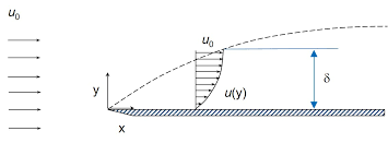
The thickness of the boundary layer ,`delta`, can be defined as that distance from the boundary in which the velocity reaches 99% of the velocity of the free stream. This definition however gives the approximate thickness of the boundary layer and is generally termed as nominal thickness of boundary layer.
The commonly accepted definition of boundary layer thickness are:
Displacement thickness
Momentum thickness
Energy thickness
Displacement Thickness:
Displacement thickness can be defined as the distance, measured perpendicular to the boundary of the solid body, by which the boundary should be displaced to compensate for the reduction in flow rate of the flowing fluid on account of the boundary layer formation.

Let us consider a fluid of density `rho` flowing with velocity U approaches a stationary plate as shown in figure. Consider an elementary strip of thickness `dy` at a distance y from the plate as shown below. Let u be the velocity of fluid at this level.
Assuming unit width of the plate, the mass flowing per second through the elemental strip is, `=rho*u*dy`
If the plate was not there, then the mass flowing per second through the elemental strip is, `= rho*U*dy`
Thus the reduction in mass flowing per second through the elemental strip due to the introduction of plate is, `=rho*(U-u)*dy`
The difference (U-u) is called the velocity of defect.
Total reduction in mass flow rate due to the introduction of plate is,
=$\int_{0}^δ ρ(U-u)dy $.... (i)
Let the plate is displaced by a distance `delta^**` and the velocity of flow for the distance `delta^**` is equal to the velocity of the free stream i.e, U. Then, the total mass of the fluid flowing per second through the distance `delta^**` is,
`=rho*U*delta^**`�?��?�(ii)
Now equating (i) and (ii), we get,
`rho*U*delta^**=\int_{0}^δ ρ(U-u)dy`
$δ^*= \int_{0}^δ ρ(1-u/U)dy$
Application of displacement thickness:
Used in wind erosion protection evaluation.
The displacement thickness is used to calculate the shape factor in order to determine the nature of flow.
Momentum Thickness:
Momentum thickness can be defined as the distance, measured perpendicular to the boundary of the solid body, by which the boundary should be displaced to compensate for the reduction in momentum of the flowing fluid on account of the boundary layer formation.
Let us consider a fluid of density `rho` flowing with velocity U approaches a stationary plate as shown in figure. Consider an elementary strip of thickness `dy` at a distance y from the plate as shown below. Let u be the velocity of fluid at this level.
Assuming unit width of the plate, the mass flowing per second through the elemental strip is, `=rho*u*dy`
The momentum per second of fluid inside the elementary area is
`rho*u*dy*u=rho*u^2dy`
Momentum per second of sake mass of fluid before entering the boundary layer is,
`rho*u*dy*U= rho*uUdy`
Loss of momentum per second in elementary area due to the introduction of plate is,
`=rho*u*(U-u)dy`
Total loss of momentum per second due to the introduction of plate is ,
$\int_{0}^δ ρ \ u(U-u)dy$... (i)
Let `theta` be the distance by which the plate is displaced to compensate for the reduction in momentum and let U be the velocity of flow.
Then, the loss of momentum per second of the flowing fluid through the distance `theta` with velocity U is,
`=rho*theta*U^2`�?�(ii)
Now equating (i) and (ii), we get,
`rhothetaU^2=\int_{0}^δ ρ( u/U )(U-u)dy`
Or, `theta= \int_0^delta u/U (1-u/U)`
Application of Momentum thickness:
It is basically used in kinetics.
It is also used to calculate the shape factor to determine the nature of flow. Shape factor is given as,`H=delta^** /theta`
Energy Thickness:
Energy thickness can be defined as the distance, measured perpendicular to the boundary of the solid body, by which the boundary should be displaced to compensate for the reduction in K.E of the flowing fluid on account of the boundary layer formation.
Let us consider a fluid of density `rho` flowing with velocity U approaches a stationary plate as shown in figure. Consider an elementary strip of thickness `dy` at a distance y from the plate as shown below. Let u be the velocity of fluid at this level.
Assuming unit width of the plate, the mass flowing per second through the elemental strip is, `=rho*u*dy`
Kinetic energy of fluid inside the elementary area per second is, `1/2mu^2=1/2 (rho*u*dy)u^2`
If the plate was not there, then the kinetic energy of the flowing per second through the elemental strip is, `= ½ (rho*u*dy)U^2`
Thus the loss in kinetic energy of flowing fluid per second through the elemental strip due to the introduction of plate is, `=1/2rho u*(U^2-u^2)*dy`
Total loss of kinetic energy per second due to the introduction of plate is,
`=\int_{0}^δ 1/2ρu( U^2-u^2 )dy`�?�.(i)
Let the plate is displaced by a distance `delta_e` ro compensate for the reduction in kinetic energy and the velocity of flow for the distance `delta_e` is equal to the velocity of the free stream i.e, U. Then, the total kinetic energy of the fluid flowing per second through the distance `delta_e` is,
`=1/2 (rho*U*delta_e)U^2`�?��?�(ii)
Now equating (i) and (ii), we get,
`1/2rho*delta_eU^2=\int_{0}^δ 1/2ρu( U^2-u^2 )dy`
Or, `delta_e= \int_0^delta u/U (1-u^2/U^2)dy`
Application of energy thickness:
It is used in the predictions of throat heat transfer in rocket nozzles.
It simplifies the Navier-Stokes equation.
5. Some Important Formulaes:
For laminar flow,
`delta/x =4.64/root ()(R_e`
Friction factor, `f=64/R_e`
`tau_0=3/2 (mu*U_0)/delta`
`C_D=1.292/root ()(R_e)`
For Turbulent flow:
`delta/x=0.371/(R_e)^(1/5)`
`C_D=0.072/(R_e)^(1/5)`
6. Write down application of Boundary Layer Theory.
APPLICATION OF BOUNDARY LAYER THEORY:
It is used in the design of airfoils of an aeroplane.
The primary practical utility of boundary layer theory is the prediction of drag (or resistance) on the body.
Important phenomenon like flow separation are defined in this theory.
It helps in the prediction and analysis of weather climate, hydrology etc.
The boundary layer theory for high Rayleigh number convection has been generalised to study convective flow.
It is used in the mixing enhancement.
It has an important application in Golf Ball Aerodynamics.
One can estimate the development of the shock over the wing.
7. Explain concepts of displacement thickness, momentum thickness and energy thickness with ir derivations.
The thickness of the boundary layer ,`del`, can be defined as that distance from the boundary in which the velocity reaches 99% of the velocity of the free stream. This definition however gives the approximate thickness of the boundary layer and is generally termed as nominal thickness of boundary layer.
The commonly accepted definition of boundary layer thickness are:
�?� Displacement thickness
�?� Momentum thickness
�?� Energy thickness
Displacement Thickness:
Displacement thickness can be defined as the distance, measured perpendicular to the boundary of the solid body, by which the boundary should be displaced to compensate for the reduction in flow rate of the flowing fluid on account of the boundary layer formation.
Let us consider a fluid of density `rho` flowing with velocity U approaches a stationary plate as shown in figure. Consider an elementary strip of thickness `dy` at a distance y from the plate as shown below. Let u be the velocity of fluid at this level.
Assuming unit width of the plate, the mass flowing per second through the elemental strip is, `=rho*u*dy`
If the plate was not there, then the mass flowing per second through the elemental strip is, `= rho*U*dy`
Thus the reduction in mass flowing per second through the elemental strip due to the introduction of plate is, `=rho*(U-u)*dy`
The difference (U-u) is called the velocity of defect.
Total reduction in mass flow rate due to the introduction of plate is,
=$\int_{0}^δ ρ(U-u)dy $.... (i)
Let the plate is displaced by a distance `delta^**` and the velocity of flow for the distance `delta^**` is equal to the velocity of the free stream i.e, U. Then, the total mass of the fluid flowing per second through the distance `delta^**` is,
`=rho*U*delta^**`�?��?�(ii)
Now equating (i) and (ii), we get,
`rho*U*delta^**=\int_{0}^δ ρ(U-u)dy`
$δ^*= \int_{0}^δ ρ(1-u/U)dy$
Momentum Thickness:
Momentum thickness can be defined as the distance, measured perpendicular to the boundary of the solid body, by which the boundary should be displaced to compensate for the reduction in momentum of the flowing fluid on account of the boundary layer formation.
Let us consider a fluid of density `rho` flowing with velocity U approaches a stationary plate as shown in figure. Consider an elementary strip of thickness `dy` at a distance y from the plate as shown below. Let u be the velocity of fluid at this level.
Assuming unit width of the plate, the mass flowing per second through the elemental strip is, `=rho*u*dy`
The momentum per second of fluid inside the elementary area is
`rho*u*dy*u=rho*u^2dy`
Momentum per second of sake mass of fluid before entering the boundary layer is,
`rho*u*dy*U= rho*uUdy`
Loss of momentum per second in elementary area due to the introduction of plate is,
`=rho*u*(U-u)dy`
Total loss of momentum per second due to the introduction of plate is ,
$\int_{0}^δ ρ \ u(U-u)dy$... (i)
Let `theta` be the distance by which the plate is displaced to compensate for the reduction in momentum and let U be the velocity of flow.
Then, the loss of momentum per second of the flowing fluid through the distance `theta` with velocity U is,
`=rho*theta*U^2`�?�(ii)
Now equating (i) and (ii), we get,
`rhothetaU^2=\int_{0}^δ ρ( u/U )(U-u)dy`
Or, `theta= \int_0^delta u/U (1-u/U)`
Energy Thickness:
Energy thickness can be defined as the distance, measured perpendicular to the boundary of the solid body, by which the boundary should be displaced to compensate for the reduction in K.E of the flowing fluid on account of the boundary layer formation.
Let us consider a fluid of density `rho` flowing with velocity U approaches a stationary plate as shown in figure. Consider an elementary strip of thickness `dy` at a distance y from the plate as shown below. Let u be the velocity of fluid at this level.
Assuming unit width of the plate, the mass flowing per second through the elemental strip is, `=rho*u*dy`
Kinetic energy of fluid inside the elementary area per second is, `1/2mu^2=1/2 (rho*u*dy)u^2`
If the plate was not there, then the kinetic energy of the flowing per second through the elemental strip is, `= ½ (rho*u*dy)U^2`
Thus the loss in kinetic energy of flowing fluid per second through the elemental strip due to the introduction of plate is, `=1/2rho u*(U^2-u^2)*dy`
Total loss of kinetic energy per second due to the introduction of plate is,
`=\int_{0}^δ 1/2ρu( U^2-u^2 )dy`�?�.(i)
Let the plate is displaced by a distance `delta_e` ro compensate for the reduction in kinetic energy and the velocity of flow for the distance `delta_e` is equal to the velocity of the free stream i.e, U. Then, the total kinetic energy of the fluid flowing per second through the distance `delta_e` is,
`=1/2 (rho*U*delta_e)U^2`�?��?�(ii)
Now equating (i) and (ii), we get,
`1/2rho*delta_eU^2=\int_{0}^δ 1/2ρu( U^2-u^2 )dy`
Or, `delta_e= \int_0^delta u/U (1-u^2/U^2)dy`
8. Explain Development of boundary layer within circular pipe.
Development of boundary layer within the circular pipe:
The development of boundary layer within a circular pipe is shown in the figure below for two cases:
When the final flow is laminar
When the final flow is turbulent
In case of pipe,all particles will start to flow with the same velocity except for the very thin film in contact with the wall as shown in the figure. As the fluid progresses along the pipe, the streamlines in the vicinity of the wall are slowed down by friction emanating from the wall, but since for steady flow the mass flow rate at the different section must be the same, the velocity in the centre must be accelerated , until the final velocity is a parabola.
Theoretically an infinite distance is required for this , but it has been established by both observation and theory that the maximum velocity in the centre of the pipe will reach 99% of its ultimate value in the distance `L_e` would be,
`L_e=0.058 R_e*D`.....(i)
In the entry region of the length `L_e`, the flow is unestablished.i.e, the velocity profile is changing.The outer zone increases in thickness as it moves along the wall , and is known as Boundary layer.
At section AB as shown in figure, the boundary layer has grown until it progresses to the entire section of the pipe. At this point, for laminar flow, the velocity profile is a perfect parabola. Beyond section AB, the velocity profile does not change, and the flow is known as established flow.
After the flow is established in laminar flow, the velocity profile is parabolic as shown in figure.
If the Reynold number is above the critical value, so that the developed flow is turbulent , the initial condition is much like that in above figure. But as the laminar boundary layer increases in thickness, a point is soon reached where a transition occurs and the boundary layer becomes turbulent,. In other words, the development starts with a laminar profile, undergoes a transition and change over to turbulent profile and stays turbulent thereafter as shown in figure. The turbulent boundary layer thickness increases much more rapidly and soon the two layers from opposite sides meet at the pipe axis and there is then fully developed turbulent flow.
The boundary layer can grow only upto the centerline of the pipe and the boundary layer thickness cannot exceed the thickness of the radius of the pipe. Since the velocity must be zero at the surface of the wall, a laminar sublayer occurs immediately next to the wall.
The rate of the growth of the boundary layer depends upon the Reynolds number as:
For laminar layer,
`delta/X=5/root()(R_e)`
And for turbulent layer,
`delta/X=0.37/R_e^0.2`
Note:Two figures are to be included here�?��?��?��?�.i.e for laminar flow and turbulent flow..they will be uploaded soon...
9. Explain hydraulically smooth and rough bounday surface.
If the irregularities on any actual surface are such that the effects of projections do not penetrate through the viscous sublayer, the surface is called hydraulically Smooth.
If the irregularities on any actual surface are such that the effects of projections extend beyond the viscous sub-layer so that the laminar layer is broken up, then such surface are hydraulically Rough surface.
From Nikuradse's experiment,
If `e/delta_v < 0.25`, the surface is smooth.
If `e/delta_v > 0.25`, the surface is rough.
where, `delta_v` is the thickness of viscous sublayer.
For hydraulically smooth pipe flow, the friction factor f is a function of Reynolds Number only.
For hydraulically Rough surface, the friction factor f is a function of only relative roughness ratio.
With increasing Reynolds Number, there is a gradual transition from smooth to rough flow.
10. Explain Boundary Layer Concept along a thin plate?
When a real fluid (viscous fluid) flows past a stationary solid boundary, a layer of fluid which comes in contact with the boundary surface, adheres to it (on account of viscosity) and condition of no slip occurs (The no-slip condition implies that the velocity of fluid at a solid boundary must be the same as that of boundary itself). Thus the layer of fluid which cannot slip away from the boundary surface undergoes retardation; this retarded layer further causes retardation for the adjacent layers of the fluid, thereby developing a small region in the immediate vicinity of the boundary surface in which the velocity of the flowing fluid increases rapidly from zero at the boundary surface and approaches the velocity of main stream. The velocity gradient will be set up and this gradient develops shear resistant which retards the fluid. So, the boundary layer develops at the leading edge.
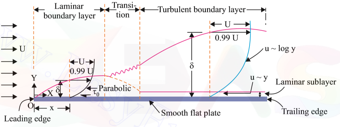
Near the leading edge of solid surface, where thickness is small, the flow in the boundary layer can be laminar and the layer is said to be laminar boundary layer. The velocity profile in the laminar layer is approximately parabolic.
As the thickness of the boundary layer increases in the downstream direction, the laminar layer becomes unstable and the motion within it will be disturbed and becomes irregular which leads to the transition from laminar to turbulent boundary layer. This zone is called a transition zone.
Further downstream the transition zone, the boundary layer is turbulent and continues to grow in thickness. The velocity profile in the turbulent boundary layer is not parabolic but follows a logarithmic law. The velocity gradient at turbulent layer is larger than that in laminar layer.
If the plate is very smooth, even in the zone of turbulent boundary layer, there exists a very thin layer immediately adjacent to the boundary, in which the flow is laminar. This thin layer is commonly known as laminar sublayer, and its thickness is represented by δ. Hence, exponential or logarithmic velocity distribution law cannot be applied within the laminar sublayer. Nikuradses experimental studies have shown that, for laminar sublayer,
`delta^'=(11.6 nu)/V^*`
Where, `V^*=root()(tau_0/rho)` is known as shear velocity.
The characteristics of a boundary layer may be summarised as follows:
δ (thickness of boundary layer) increases as distance from leading edge x increases.
δ decreases as U increases.
δ increases as kinematic viscosity (`nu`) increases.
`tau_0~~(muU)/delta`; hence `tau_0` decreases as x increases. However, when boundary layer becomes turbulent, it shows a sudden increase and then decreases with increasing x.
When U increases in the downward direction, boundary layer growth is reduced.
When U decreases in the downward direction, flow near the boundary is further retarded, boundary layer groExplain the concept of Boundary Layer.
The various characteristics of the boundary layer on flat plate (e.g variation of δ, `tau_0` or force F) are governed by inertial and viscous forces; hence they are functions of either `Ux/nu` or `UL/nu` .
If `(Ux)/nu <5`*`10^5`,boundary layer is laminar (velocity distribution is parabolic).
If `(Ux)/nu >5`*`10^5`,boundary layer is turbulent on that portion (velocity distribution follows Log law or a power law).
Though the velocity distribution would be a parabolic curve in a laminar sub-layer zone, for small thickness we can assume the velocity distribution to be linear.
All Chapters
Dimensional Analysis, Similitude and Physical Modelling
Flow Past Through Submerged Body
Boundary Layer Theory
Properties of fluid
- properties of fluids
- complete IOE solution on fluid mechanics
- Detailed description chapterwise
- Unlimited Numericals problem solved with updation daily
- And much more
Hydrostatics
- Hydrostatics basic theory
- All important Numericals
- IOE,PU, MIT,A.M.I.E,Delhi university,EUPS,Engineering service exam solved problems
- Detailed explanation
Hydrostatics- Buoyancy and metacentric height
- detailed explanation of force of buoyancy, metacentric height,stability of floating body
- unlimited numericals solved with updation weekly
- including IOE , PU, KU, GATE, MIT, ANNA UNIVERSITY,UPSC EXAM SOLUTIONS
- And much more
